Blog
Flexible Versus Rigid Ducting: Which Fits?

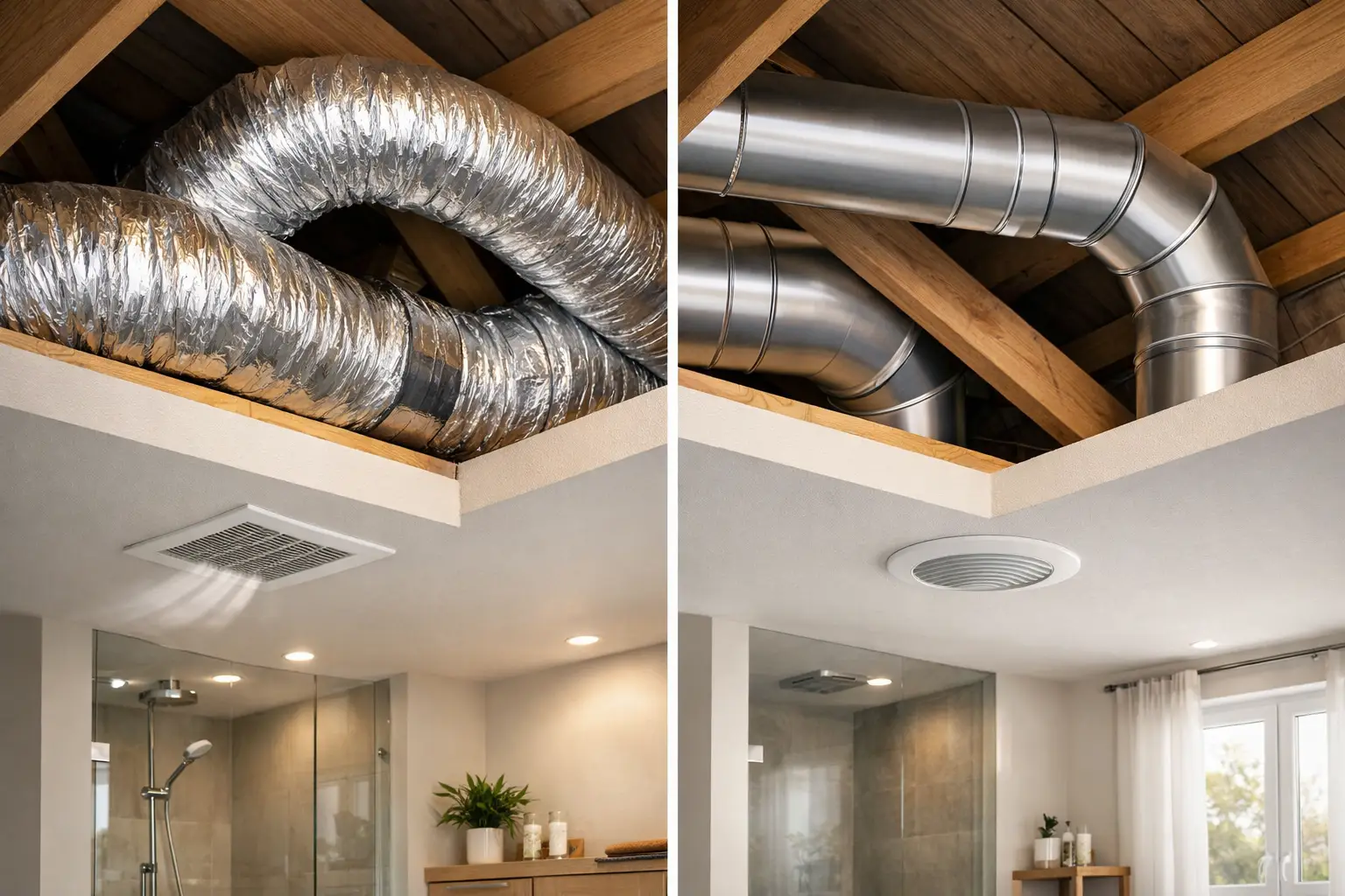
A bathroom fan can have the correct airflow rating and still leave condensation on the mirror if the duct run creates too much resistance. That is the practical issue behind flexible versus rigid ducting: the duct is not merely a connection between fan and outside grille. Its diameter, internal surface, length, number of bends and installation quality directly affect extracted airflow, noise and the fan’s working pressure.
For most domestic extract systems, rigid ducting gives the best airflow performance over a permanent run. Flexible ducting remains useful, and sometimes essential, where access is restricted or a short final connection needs to absorb movement. The right choice depends on the whole system rather than the convenience of fitting one section.
Flexible versus rigid ducting: the key difference
Rigid ducting has a fixed shape, commonly circular plastic duct or galvanised steel duct. Its smooth internal bore lets air travel with relatively low friction, particularly through straight sections. Correctly selected fittings provide controlled direction changes and allow the duct route to remain properly supported.
Flexible ducting is typically a spiral-supported material that can bend around obstacles without separate elbows. It is quick to route through ceiling voids, service cupboards and confined spaces. However, its internal surface is less smooth, and a flexible duct that is compressed, sagging or sharply bent produces substantially more resistance than a straight, fully extended section of the same nominal diameter.
That resistance matters because an extractor fan delivers its published airflow under stated test conditions. Each metre of duct, bend, external grille, backdraught shutter and filter adds system pressure. If resistance rises beyond what the fan can overcome, actual airflow falls. In a bathroom, that can mean slower humidity removal; in a kitchen or utility room, it can mean moisture and odours remain for longer.
Why rigid ducting usually performs better
A rigid circular duct is the preferred option for long runs and for fans expected to operate close to their designed duty. Smooth walls reduce friction losses, while formed bends can be chosen and positioned to avoid tight turns. Circular duct also maintains its full cross-sectional area, provided couplers and reducers are correctly matched.
This is especially relevant for inline duct fans, which are often used where air must travel through a loft, ceiling void or longer route to an external wall or roof terminal. An inline fan may be capable of handling more pressure than a basic axial bathroom fan, but it still benefits from a low-resistance duct route. Installing a higher-pressure fan does not make poor duct design irrelevant.
Rigid ducting can also reduce transmitted airflow noise. Turbulence increases where air passes over corrugations, through crushed sections or around abrupt changes in direction. A smooth, correctly sized rigid run helps keep air velocity and turbulence under control. It will not remove motor noise or eliminate the need for appropriate fan selection, but it avoids adding unnecessary duct noise.
There are trade-offs. Rigid duct requires planning, accurate cutting and sufficient access for fittings. In renovation work, joists, pipes, cable routes and structural constraints can make a perfectly straight route impossible. It is also less forgiving where the fan outlet, duct penetration and terminal are not precisely aligned.
Circular, flat and rectangular duct choices
Round duct is generally the most efficient shape for a given airflow because it has a favourable internal geometry and widely available compatible fittings. Where space is limited, flat or rectangular plastic duct can be a practical alternative, particularly above suspended ceilings or within boxed-in services.
The limitation is that flat duct must be selected by its equivalent airflow capacity, not simply by its visible width. A shallow channel may have a smaller effective area than the round duct it replaces, increasing velocity and pressure loss. Check the manufacturer’s compatibility information for the fan, duct system, bends and external terminal before changing duct shape or reducing size.
Where flexible ducting makes sense
Flexible ducting is not automatically a poor choice. It is useful for short sections where rigid components cannot be aligned easily, such as the connection between an inline fan and fixed ductwork, or a final connection to a ceiling valve where a small amount of adjustment is needed. It can also help isolate vibration in an otherwise rigid installation, although it is not a substitute for proper fan mounting and support.
The best flexible installation is short, fully extended and gently curved. Support it so it cannot sag, and avoid routing it around sharp corners. A long loop of unsupported flexible duct is one of the most common causes of avoidable airflow loss. It creates more internal drag, collects dust more readily and can hold condensation if the route passes through a cold space.
Insulated flexible duct has a distinct role where warm, moisture-laden extract air passes through an unheated loft or other cold zone. Insulation can reduce the likelihood of condensation forming on the duct exterior or inside the duct run. It should still be installed without compression and with an appropriate route. If condensation risk is significant, the duct may need a slight fall towards the external side or another planned drainage approach, depending on the system design.
Do not use standard flexible duct as a convenient way to make repeated tight bends. Every bend should have the largest practical radius. If a route needs several direction changes, rigid duct and swept fittings will normally give a more predictable result.
Diameter matters as much as material
Changing from rigid to flexible duct is often less damaging than reducing duct diameter, but both decisions must be assessed together. A fan with a 125 mm outlet should not be reduced to 100 mm simply because the smaller duct is easier to conceal. The reduction decreases duct area and increases air velocity, pressure loss and noise.
Maintain the fan’s specified duct diameter for as much of the route as possible. If a reduction is unavoidable, confirm that the fan has adequate pressure capability for the final system resistance. This is particularly important with humidity-controlled fans, timer fans and continuously running ventilation units, where a restricted duct can prevent the expected extraction rate from being achieved.
External grilles and roof terminals also need matching attention. A terminal with insect mesh, a gravity flap or a small free area can add meaningful resistance. Choose components intended for the duct diameter and application, and avoid placing restrictions immediately at the fan outlet where possible.
A practical route for bathroom extraction
For a typical bathroom, a sensible arrangement is a short, direct rigid duct route from the fan to an external terminal, using the fewest practical bends. Where a short flexible connector is needed for alignment, keep it taut and accessible for inspection. If the route passes through a cold roof void, consider insulation and support as part of the installation rather than an optional finishing detail.
For a long route, an inline fan may be more suitable than relying on a standard wall-mounted axial fan to pull air through several metres of duct. The selection should be based on the required airflow at the expected system pressure, not on free-air airflow alone. Fan performance curves, where available, are more useful than a single maximum airflow figure.
Installation details that protect airflow
Whichever duct type is chosen, joints should be correctly connected, sealed where required and mechanically secured. Air leaks in a loft or ceiling void reduce extraction at the room terminal and may release humid air into the building fabric. Use compatible couplers, bends, clips and sealing materials rated for the duct material and operating conditions.
Support rigid duct at sensible intervals so it cannot pull apart at joints. Support flexible duct more frequently, using broad supports that do not pinch the material. Keep duct routes accessible where maintenance is likely, especially around fans, condensate-prone sections and terminals.
Avoid unnecessary backdraught shutters in series. A fan may already have an integral shutter, while the external terminal may include another. Two restrictive flaps can create rattling, reduced airflow or unreliable opening at low fan speeds. Check the system as a whole before adding accessories.
Choosing the right duct for the job
Choose rigid ducting as the default for permanent straight runs, longer routes, higher airflow systems and installations where low noise matters. It is the most dependable way to preserve fan performance and make future cleaning or modification easier.
Choose flexible ducting for short, carefully installed connections, difficult access points and situations where movement or alignment tolerance is needed. Treat it as a controlled connector rather than an all-purpose duct route. Insulated flexible duct is appropriate where thermal conditions justify it, but it still needs to remain extended and supported.
For mixed installations, the strongest approach is often rigid duct for the main route with the minimum necessary flexible section at the fan, valve or terminal. This balances installation practicality with lower resistance and more predictable extraction.
Before ordering, map the route, measure the required diameter, count bends and check the fan outlet, duct fittings and terminal compatibility. A well-chosen fan can only deliver healthy airflow if the duct behind it gives that air a clear route out of the building.